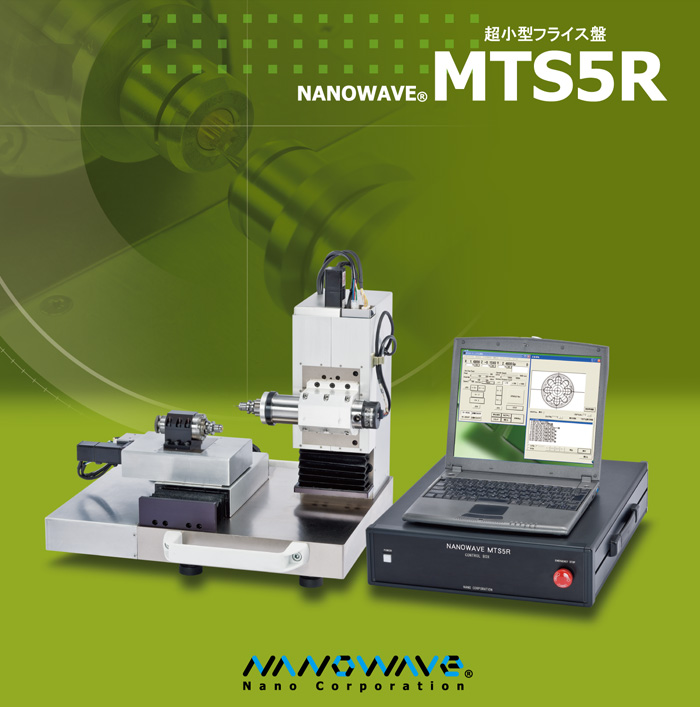
Super-small precision milling machine NANOWAVE MTS5R
Main features
- This is a super-small milling machine measuring 414X450X470mm that requires the world's smallest footprint.
- By changing specifications, this can be used as milling machine, lathe or polish processing machine.
- The open space machine structure without a cover makes the tool and workpiece easy to be fixed.
- Since operation is carried out based on PC, it does not require difficult manipulation technology.
- The main spindle has a maximum revolution of 20,000min-1, and with reduction of runout to the least, machining of small bore holes with a diameter of less than 0.1mm is possible.
- The main spindle runout is less than 2μm. (It can be less than 1μm by adjustment.)
- There is a through-hole of φ3 in the main spindle, and in the case of lathe specifications, processing of long materials is possible.
- Difficult-to-cut-materials such as cemented carbide will also be processable.
- NANOWAVE MTS5R has been designed and manufactured all in-house by our company.
Processing examples
- Machining of stepped thin pin
- Workpiece: brass
- Machining dimensions: φ0.1mm, 0.2mm, 0.3mm
- Grooving of glass
- Workpiece: soda glass
- Machining dimensions: groove width 0.4mm x depth 0.05mm
- Fine mold processing
- Workpiece: φ5 brass
- Machining dimensions: Hole 1mm x 1mm, Center pin 0.2mm
- Waveform-shaped grooving
- Workpiece: brass plate
- Machining dimensions: Groove width 0.3mm, R0.3
For other processing examples and how to utilize, see here.
Information including outer dimensions and weights of products and detailed dimensions of tables are shown in the product catalogues. Please download them at the Catalogue PDF in the above.
MTS5R milling machine (Standard-type) Mechanical Specifications
| Items | Specifications | Remarks | |
| Structure | Horizontal milling machine structure (※Applicable to vertical milling machine structure) | ||
| Processing range | Recommended processing range | About 60 x 30 x 5mm | |
| Table | Stroke | X: 100mm/Y: 50mm/Z: 30mm | |
| Size of work area (Z axis stand-side) | 83 x 65mm | ||
| Max. movable weight | 5kg | ||
| Least command increment | 0.0001mm | ||
| Rapid feed speed | Max. 6,000mm/min | ||
| Guide face | Cross roller guide | ||
| Feed screw | Precision ball screw | ||
| Straightness of each surface when moving | Within 0.002mm/100mm (※Within 0.001mm/100mm is possible.) | ||
| Repeated positioning accuracy | ±0.001mm | ||
| Main spindle | Number of revolution | ±0.1 to 20,000min-1 | |
| Unit of angle positioning | 1deg. | ||
| Simultaneous operation/thread cutting operation | Possible. | ||
| Chuck type | Collet chuck | ||
| Range of gripping diameter φ0.2 to 10.0mm (※For diameter requirement with fraction, please consult us.) | φ0.2 to 10.0mm (※For diameter requirement with fraction, please consult us.) | ||
| Main spindle through-hole | Processing is possible (φ3mm or less) | ||
| Accuracy of main spindle runout | 2μm or less (※1μm or less is possible) | ||
| Workpiece holder | Precision vice | For fixing block material | Optional |
| Round workpiece holder | For fixing round bar material | Optional | |
| T-grooved bed | Universal bed (※We also make holders of special specifications) | Optional | |
| Required power source | Power source | AC100V 70W | |
| Air pressure source | 0.5MPa, 10NL/min | ||
| Dimensions | Machine | W560 x D620 x H505mm | |
| Control box | W370 x D450 x H180mm | ||
| Weight | Machine | 65kg | |
| Control box | 16kg | ||
| Options | Oil mist feeding device | Chip removal & coolant (※Compressed air source is required separately.) | |
NC device specifications
●:Standard ○:Optional
| Items | Specifications | Remarks | ||
| NC type | PC NC | Windows 98/NT/2000/XP/7(PC-AT) 32bit version | ● | |
| Connection method | USB connection | USB2.0 | ● | |
| Code system | G code | ● | ||
| Control axis | Control axis | X, (Y), Z, S (Main spindle) | ● | |
| No. of simultaneous control axis | Positioning: 4/linear interpolation:4/circular interpolation:2 | ● | ||
| Minimum setting unit | 0.0001mm (X/Y/Z axis) | ● | ||
| 1°(Main spindle) | ● | |||
| Manual operation | Zero return | ● | ||
| Jog operation | ● | |||
| Inching operation | ● | |||
| Manual pulser operation | ○ | |||
| Sub spindle operation | ○ | |||
| Feed function | Rapid feed speed | Max. 6,000mm/min | ● | |
| Speed override | 0 to 200% | ● | ||
| Tool length compensation | ● | |||
| Program operation | NC program | Maximum block number (in automatic operation mode) | 888 blocks | |
| DNC operation | ● | |||
| Subprogram | No. of setting labels in 1 program | Max. 100 pcs | ● | |
| (In automatic operation mode) | No. of repeated readouts | Max. 50,000 times | ● | |
| No. of nesting | Max. 20 times | ● | ||
| Single block | ● | |||
| Macro functions | ○ | |||
| Applicable G code | Movement command | Absolute command | G90 | ● |
| Incremental command | G91 | ● | ||
| Rapid feed | G00 | ● | ||
| Linear interpolation | G01 | ● | ||
| Circular interpolation | G02 (CW circular interpolation) | ● | ||
| G03 (CCW circular interpolation) | ● | |||
| Helical movement | G02 (CW helical movement) | ● | ||
| G03 (CCW helical movement) | ● | |||
| Dwell | G04 | ● | ||
| Thread cutting | G33 | ● | ||
| Positioning finish check | G61 (With positioning finish check) | ● | ||
| G64 (Without positioning finish check) | ● | |||
| Program stop | M00 | ● | ||
| Optional stop | M01 | ● | ||
| Mechanical coordinate system absolute command | G28 | ● | ||
| Feed speed | Feed per minute | G94 F* | ● | |
| Feed per revolution | G95 F* | ● | ||
| Main spindle command | Continuous normal rotation | S* / M03 (Main spindle normal rotation) | ● | |
| Continuous reverse rotation | S-* / M04 (Main spindle reverse rotation) | ● | ||
| Stop | S0 / M05 (Main spindle stop) | ● | ||
| Rotation angle positioning | C* | ● | ||
| Tool command | Tool designation/tool change | T* | ● | |
| End of program | End of program | M30 | ● | |
| Coordinate change/setting | Tool diameter compensation/nose R compensation | G40 (Cancelling Tool diameter/nose R compensation) | ● | |
| G41 (Tool diameter/nose R compensation - LH side) | ● | |||
| G42 (Tool diameter/nose R compensation - RH side) | ● | |||
| Workpiece coordinate system (Off-line setting) | G54 - G59 | ● | ||
| Workpiece coordinate system (Setting during execution) | G92 | ● | ||
| Coordinate plane designation | G17 (XY plane) | ● | ||
| G18 (ZX plane) | ● | |||
| G19 (YZ plane) | ● | |||
| Program laborsaving | Subprogram | M98 (Calling) | ● | |
| M98 (Calling) | ● | |||
| Outer/inner diameter rough cutting cycle | G71 | ● | ||
| End face rough cutting cycle | G72 | ● | ||
| Closed-loop cutting cycle | G73 | ● | ||
| Finishing cycle | G70 | ● | ||
| Outer/inner diameter cutting cycle | G77 | ● | ||
| Single thread cutting cycle | G78 | ● | ||
| End face cutting cycle | G79 | ● | ||
| Spot drilling cycle | G81 | ● | ||
| Spot drilling cycle dwell | G82 | ● | ||
| Peck drilling cycle (high-speed deep hole) | G83 | ● | ||
| Peck drilling cycle (detail) | G84 | ● | ||
| Boring cycle cancellation | G80 | ● | ||
| Boring cycle zero return | G98 | ● | ||
| Boring cycle return to point R | G99 | ● | ||
| Peripheral devices control | Universal contact point ON/OFF | M11 to M18 (Channel 1 to 8 contact points ON) | ● | |
| M21 to M28 (Channel 1 to 8 contact points OFF) | ● | |||
| Sub spindle control | A1 to 8 S* (A1 to 8 Normal rotation/reverse rotation/Stop) | ● | ||